
Examine the Readout on the Variable Frequency Drive (VFD)
Overview/Background Information
What Steps Have I Already Taken?
Before You Begin
If you haven't yet done so:
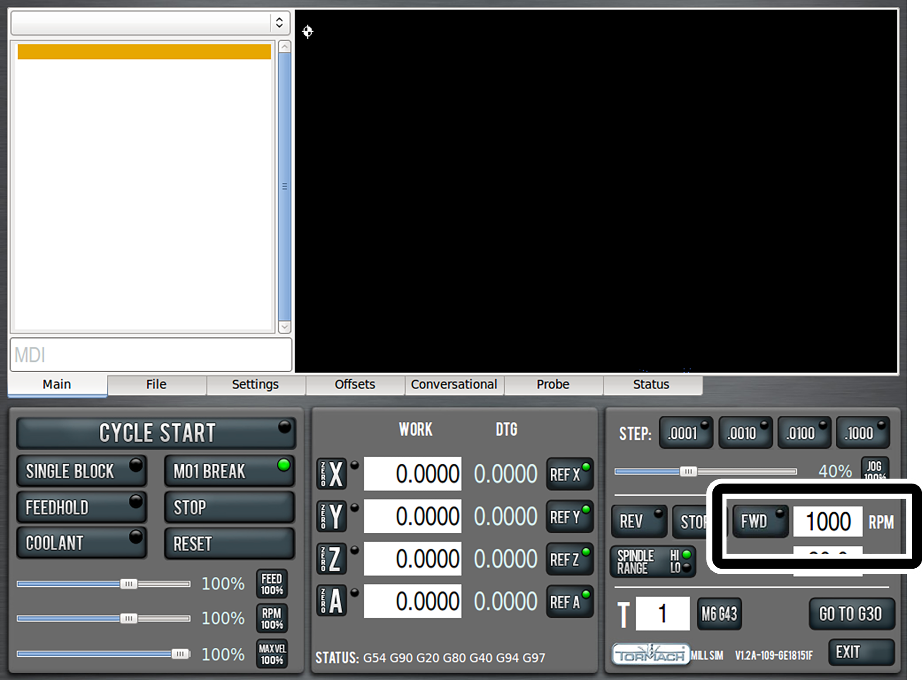
- From the PathPilot® interface, in the RPM DRO field, type 1000 and press ENTER on the keyboard.
-
Click FWD.

-
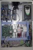
Open the electrical cabinet door.
WARNING! Electrocution Hazard: When servicing the machine from inside the electrical cabinet, always use caution. Points in the electrical cabinet have high voltages that can electrocute or shock you. Even after you've powered off the machine, electronic devices in the electrical cabinet may retain dangerous electrical voltages. Only qualified electrical machinery technicians should perform maintenance or troubleshooting procedures inside the electrical cabinet while power is still on.
-
Locate the variable frequency drive (VFD).

Troubleshooting Steps
-
Examine the VFD readout.
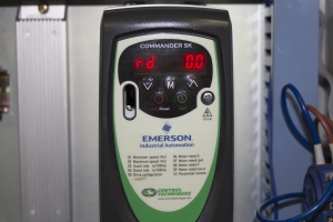

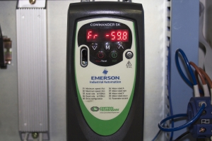
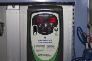
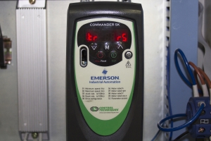

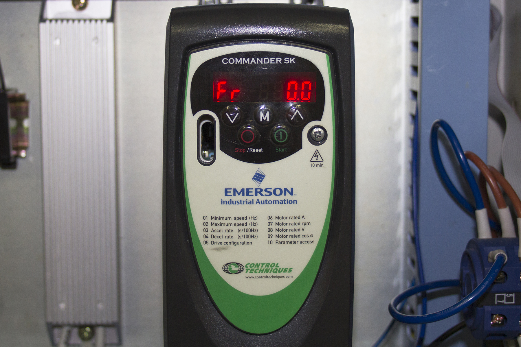

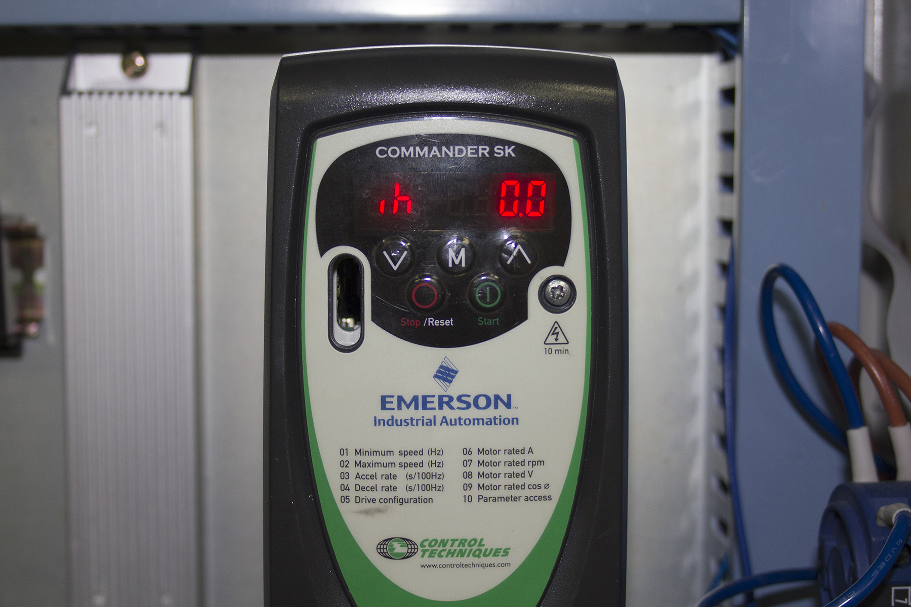

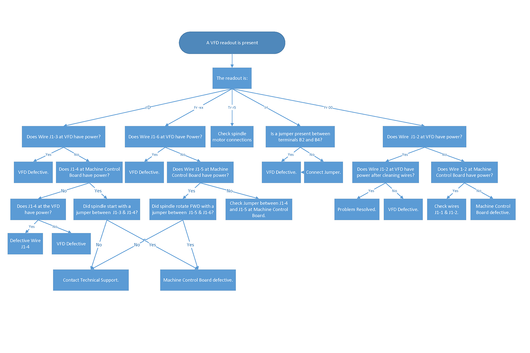
Do you see any entries in the VFD readout?
- Yes, the VFD readout displays rD: Go to Measure the Voltage on Wires J1-2 and J1-3.
- Yes, the VFD readout displays Fr 0.0: Go to Measure the Voltage on Wires J1-1 and J1-2 on the Variable Frequency Drive (VFD).
- Yes, the VFD readout displays FR -[NUMBER.NUMBER], and the spindle only rotates in the reverse direction: Go to Measure the Voltage on Wires J1-2 and J1-6.
- Yes, the VFD readout displays ih: Go to Examine the Jumper Connection Between Terminals B2 and B4.
- Yes, the VFD readout displays tr r5: Examine the system for a Quick-Change Motor Connection Kit and reconnect if necessary.