How Spindle Commands are Processed
The PathPilot® operating system sends a speed command (0 to 10 kHz on pin 1 of cable DB25) and a direction signal (pin 16) to the
- Reads the speed command.
- Determines the state of the Spindle Mode switch on the operator panel.
-
Decides whether or not to send the 24 Vdc Run signal to the VFD.
NOTE: If there is 24 Vdc, it sends a Run signal. If there is 0 Vdc, it sends a Stop signal.
-
Decides whether or not to send the 24 Vdc Forward signal to the VFD.
NOTE: If there is 24 Vdc, it sends a Forward signal. If there is 0 Vdc, it sends a Reverse signal.
- Translates the speed command (0 to 10 kHz) into an analog voltage (0 to 5V).
While this is in progress, the green Activity LED on the
NOTE: The speed at which the green Activity LED flashes is proportional to the spindle speed command sent from PathPilot®.
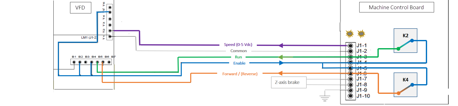
Enable Commands
The VFD sends an enable signal to the
Run Commands
After PathPilot® signals a Run command to the
If rD displays in the VFD readout, the VFD is ready (enabled) but is not receiving a Run command on J1-3.
Forward Commands
After PathPilot® signals a Forward command to the
If Fr -[NUMBER.NUMBER] displays in the VFD readout and the spindle only rotates in reverse, the VFD is not receiving a Forward command on J1-6.
Speed Commands
The
When the spindle is operating at full speed, the signal is 5V.
From the VFD readout, you can determine the following:
- If Fr 0.0 displays, the VFD is receiving enable and run commands, but is not receiving a speed command. Fr [NUMBER].[NUMBER] indicates the spindle speed voltage frequency.
- If iH displays in the VFD readout, the VFD is prevented from operating. Check the jumper connections between terminals B2 and B4 on the VFD.
- If Tr displays in the VFD readout, the VFD circuit is open. Check motor connections, especially if a