Overview of Spindle Operation
If your machine's spindle won't start, there are many tips and procedures that you can follow to solve the problem. Go to Troubleshooting Spindle Start Issues.
If you want detailed information on how the spindle operates, see the following section, Overview of Spindle Operation.
Overview of Spindle Operation
NOTE: Depending on your machine and options, not all of the features described here may apply. For example, a machine with an optional full enclosure has the Operator Panel removed, and the Control Relocation Kit included.
For the spindle to operate, the:
- Machine must be out of reset and referenced before the PathPilot® controller is able to issue a spindle command
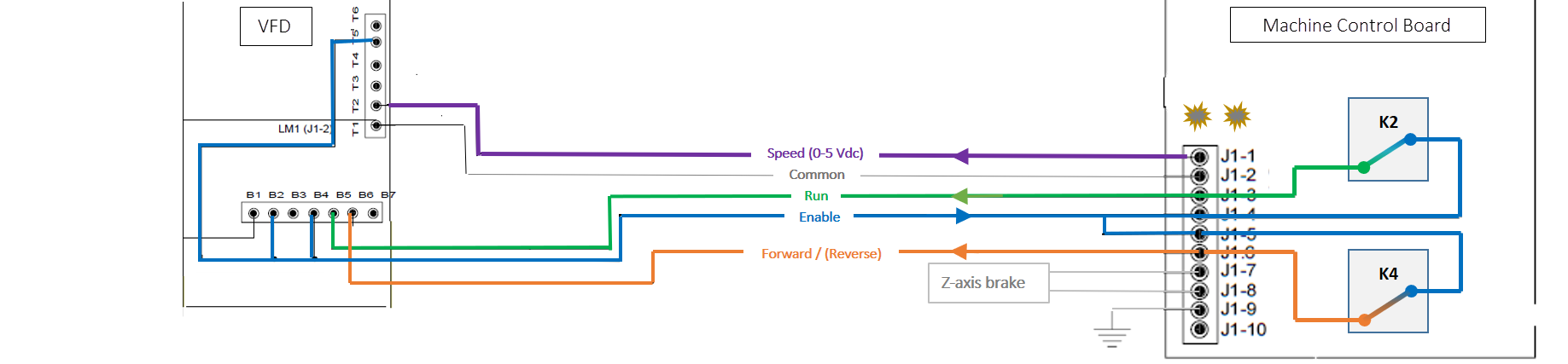
- Variable frequency drive (VFD) must have power, run and enable signals, and a speed command
Once those conditions are met, the spindle starts when — from the PathPilot® interface — you type a valid RPM number in the RPM DRO field, click FWD, and then press ENTER on the keyboard.
How Spindle Commands Are Processed
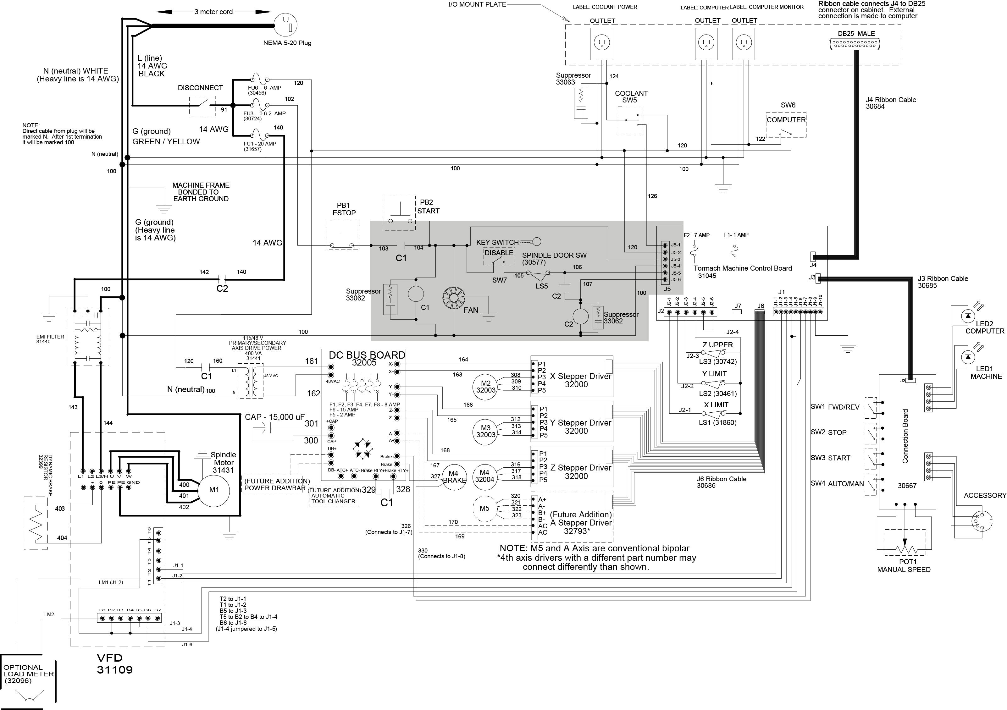
The PathPilot® operating system sends a speed command (0 to 10 kHz on pin 1 of cable DB25) and a direction signal (pin 16) to the
- Reads the speed command.
- Determines the state of the Spindle Mode switch on the operator panel.
-
Decides whether or not to send the 24 Vdc Run signal to the VFD.
NOTE: If there is 24 Vdc, it sends a Run signal. If there is 0 Vdc, it sends a Stop signal.
-
Decides whether or not to send the 24 Vdc Forward signal to the VFD.
NOTE: If there is 24 Vdc, it sends a Forward signal. If there is 0 Vdc, it sends a Reverse signal.
- Translates the speed command (0 to 10 kHz) into an analog voltage (0 to 5V).
While this is in progress, the green Activity LED on the
NOTE: The speed at which the green Activity LED flashes is proportional to the spindle speed command sent from PathPilot®.
Enable Commands
The VFD sends an enable signal to the
Run Commands
After PathPilot® signals a Run command to the
If rD displays in the VFD readout, the VFD is ready (enabled) but is not receiving a Run command on J1-3.
Forward Commands
After PathPilot® signals a Forward command to the
If Fr -[NUMBER.NUMBER] displays in the VFD readout and the spindle only rotates in reverse, the VFD is not receiving a Forward command on J1-6.
Speed Commands
The
When the spindle is operating at full speed, the signal is 5V.
From the VFD readout, you can determine the following:
- If Fr 0.0 displays, the VFD is receiving enable and run commands, but is not receiving a speed command. Fr [NUMBER].[NUMBER] indicates the spindle speed voltage frequency.
- If iH displays in the VFD readout, the VFD is prevented from operating. Check the jumper connections between terminals B2 and B4 on the VFD.
- If Tr displays in the VFD readout, the VFD circuit is open. Check motor connections, especially if a
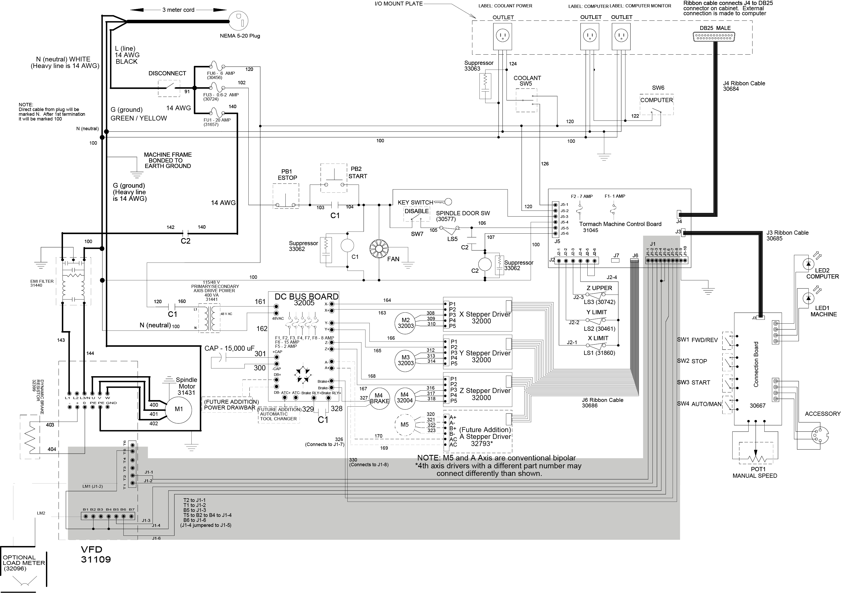
How Power is Controlled
The
During operation, contactor C2 engages when you first command the spindle to run, and remains engaged until you (or the machine) do any one of the following actions:
- Open the spindle door
- Turn the Spindle Lockout key to thelocked ("0" position)
- The
To prevent injury, the spindle door switch stops power to the spindle when the spindle door is open. Wires 105 and 106 are connected from the contactor C2 coil to the spindle door switch. The spindle doesn't start if:
- The spindle door is open,
- The switch is faulty or not properly adjusted, or
- Wires 105 and/or 106 are loose.
When you turn the Spindle Lockout key to the locked ("0" position), the system stops power to the VFD. Wires 104 and 105 are connected from the contactor C2 coil to the Spindle Lockout switch. The system doesn't supply power to the VFD if:
- The switch is faulty or not properly ajusted, or
- Wires 104 and/or 105 are loose.
If you have the optional
-
- Relay is faulty
- Wires 105 and/or 105A are loose