
How Limit Switch Commands are Processed
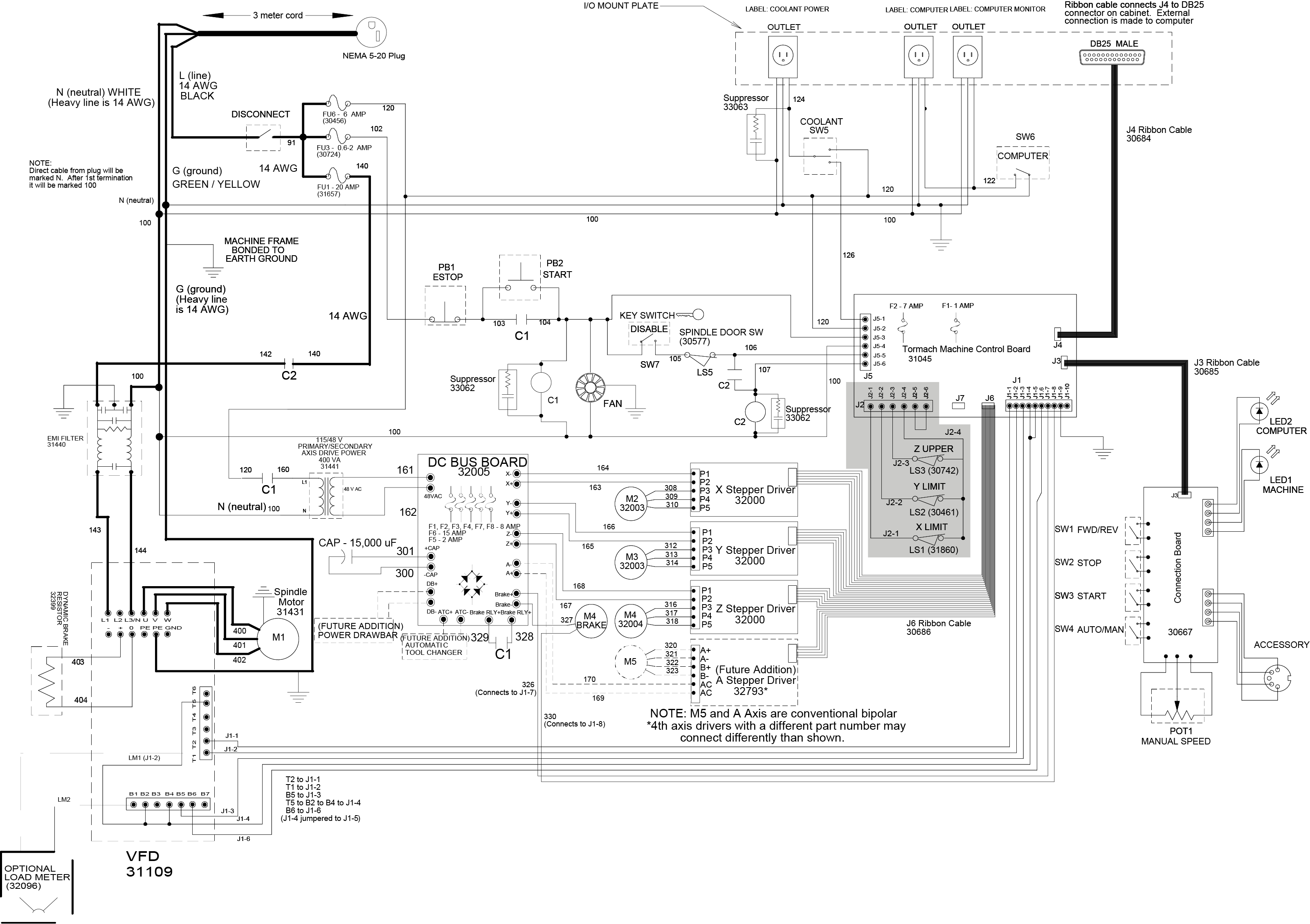
Each limit switch is connected to the J2 terminal on the
The following happens when you click REF Z, REF X, or REF Y from the PathPilot® interface:
- The machine table or column moves to the Z, X, or Y limit switch. The limit switch circuit opens, and the axis motor stops.
- The machine table or column reverses axis motion direction a small distance until it's off of the limit switch. The limit switch circuit closes.
- A soft limit is created for PathPilot® operation.
If you click REF Z, REF X, or REF Y, and one or more limit switch circuits is open, the axis will not begin the referencing procedure.
If the limit switch circuit is not open at the end of the referencing procedure, PathPilot® continues to reference the axis at the end of travel: the axis motor stalls and makes a chattering sound.